Compaq Presario 2100 RAM Upgrade Procedure

If you’ve got a slightly older notebook suck as the Compaq/HP Presario 2100 series, you might be feeling that the performance is somewhat lack-luster compared to more modern laptops. There are fewer upgrade options for laptops when compared with desktops but the most obvious upgrade is to increase or even ‘max-out’ the installed RAM.

Thankfully, the procedure for upgrading RAM on the Presario 2100 series is very straight-forward. The RAM bay is located on the underside of the machine and requires only the removal of two screws for access. The model featured here is actually a 2103EA which is a little known/unheard of model which resembles the specification of the 2103EU/2103US. Most of the other 210x models are generally similar.

The Upgrade

First, disconnect the power supply from the system. Then remove the battery by pulling up on the battery release catch while pulling on the battery itself as shown below.
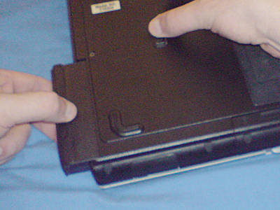
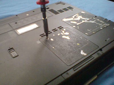
Locate the RAM bay which is on the base of the machine underneath the touchpad. Using a fine Philips (cross-head) screw-driver, undo the two screws on this panel. Note that the screws are ‘captive’ and will not come all the way out (Top marks to Compaq/HP on this feature!). Only unscrew them enough to release the panel.
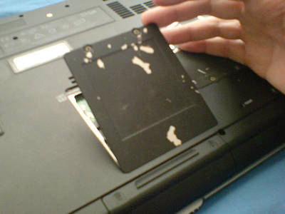
The panel then lifts up from the edge containing the screws and slides out of the locating lugs at the other end.
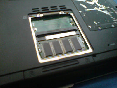
You will now see the two SO-DIMM RAM slots (one populated here). Insert your new SO-DIMM into the available slot(s) making sure to match the locator ‘key’ to the raised locator in the slot itself. This prevents reverse installation of the RAM. The RAM just pushes down until the two retaining clips at the outside edge clip it into place, holding it flat. In order to remove a SO-DIMM module, simply push the two clips outward and the module will spring up.
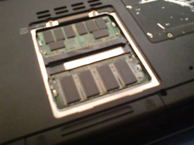
To finalise the job, replace the RAM bay cover and refasten the retaining screws. Reinsert the battery and reconnect the power supply.

On powering your machine up again, you can hit F2 during the POST and enter the BIOS config. On the first page, you should see the installed RAM figure. This will be less than the installed amount depending on how much is given over to (shared)video memory. The video memory amount is also displayed here and can be adjusted.

Hopefully, when you boot into your OS of choice, you should see an improvement in performance. RAM is relatively cheap in Europe and the USA right now so it’s probably the best time to purchase this kind of upgrade.

Maximum amount of installable RAM for Presario 2100 Series

To the best of my knowledge, the 2100 series laptops ‘max-out’ at 1GB of RAM due to each of the two banks being limited to 512MB by the 320M chipset on the motherboard.

The original SO-DIMM modules were apparently PC2100 units but I’ve now installed PC2700 units with no ill-effect. The PC2700 RAM simply runs at the lower PC2100 speed.

I strongly recommend searching for RAM specifically designed for your system. I used Offtek UK who supplied me with a Buffalo PC2700 512MB module for around £12 delivered.

Always check with the supplier that the RAM you are ordering matches your laptop (some laptops can be extremely picky about which modules they will work with.

Disclaimer: The above may be incomplete or inaccurate; attempt entirely at your own risk! 😉

[ad name=”articlebox10″]

Morex T3310 + Epia EX1000 + Mythbuntu

I first set up a MythTV system for my relatives a few years ago (at MythTV 0.19 IIRC) as a research system and soak-testing platform (you can’t beat free R&D testers). MythTV at the moment is great if you’ve got a technician available on call to support it but I couldn’t see myself deploying it to a customer yet. After all, MythTV at 0.21 is still billed as Alpha software and it would be rather silly to operationally deploy Alpha software 😉 The MythTV system consisted of a P4 based backend server with DVB encoder cards and a frontend machine in the lounge. Originally it ran on a SuSE based platform but this later changed to Ubuntu and then Mythbuntu based by the time 0.21 came around.

The original frontend was built on a Biostar barebones system which was styled as a ‘shuttle’ PC. Unfortunately, while not all that loud, the combination of cooling fan and disk drive sound was perhaps a bit much for quiet living-room TV watching situation. Further, being a ‘full-size’ AMD Sempron based system with a 3.5″ IDE hard drive for the operating system and Geforce 5600 video, it was a bit power-hungry by modern standards. I’d have estimated that it would be drawing around 140 Watts in operation.

To remedy the situation, I first tried to convince my relatives that watching television would only rot their brains and that they should find an alternative pastime but to no avail. Instead I had to come up with a solution to replace the Biostar box.

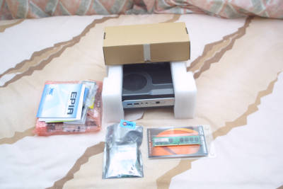
I decided to go with a Mini-ITX solution and sourced a B-stock Epia EX1000 from ebay. The EX1000 is a fanless Mini-ITX board from VIA with a 1Ghz C7 processor and a CX700 chipset.

Obviously, a fanless motherboard would want a fanless case to go with it and after a bit of deliberation, I sourced a Morex T3310 from Lin-ITX in the UK. The Morex T3310 is based upon the earlier Morex T3300 which did have a fan. To facilitate fanless cooling on the T3310, large vents are cut in the sides and top of the case. The integrated 60W (12v supply) PSU sits uppermost in the case so heat rising from it leaves through the top vent without causing undue heating to the motherboard below.

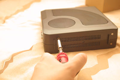
Getting the case apart to fit the motherboard is a *little* tricky so I’ve documented it here. I must apologise for the quality of the pictures, I hadn’t intended to photograph the process and used the wrong camera settings.

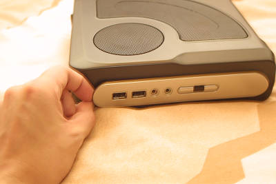
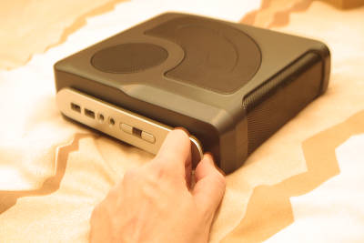
Firstly, the plastic front panel which shrouds the USB ports and power/HDD LEDs must be removed. While the plastic isn’t unusually flimsy, you’ll want to take a bit of care during removal. Use only your fingers, do not attempt to force the panel off with tools.

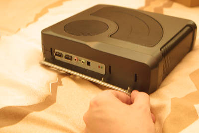
Lever gently at either end to release the clips.

There is a third clip in between the two outer clips and adjacent to USB ports. This should come away when the nearest out clip is released.

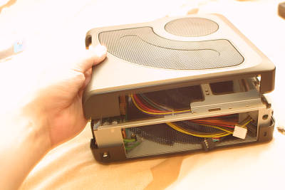
The correct side of the case must now be unscrewed. This is helpfully referred to as the ‘left’ side of the case in the Morex instructions which fail to give a reference of looking from the front or back. As it happens you can identify the correct side to remove by looking through the meshes and finding the side which has the 2.5″ HDD carrier plate nearest it.

You only need to unscrew the two screws on this side. With the two screws out, you carefully pull the two sides apart from the bottom (screw end) of the case, the upper edges will then unclip from each other too.

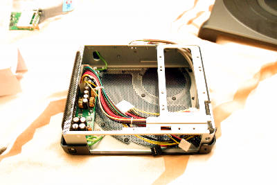
This should leave you with the case open and ready to accept your mini-itx board.

Continue reading

Brother HL 5030 (and others) drum counter reset

As much for the benefit of my own memory as for yours, I briefly detail here the drum counter reset procedure for the Brother HL 5030 laser printer (and probably most of the HL 5xxx range).

The HL 5030 has an internal counter which basically registers pages printed (apparently with weighting for cold and hot starts). This counter can be reset when replacing a drum or if you just want to run your existing drum into the ground (the HL 5030 is an older model now).

Counter Reset Procedure.

  1. Power on (Drum light should be flashing).
  2. Open the toner cartridge access door (big door on the front).
  3. Remove the toner cartridge by pulling on it.
  4. Reinsert the toner cartridge (give it a good shove).
  5. Press and hold the ‘GO’ button for about four seconds. The led indicators should come on one-by-one in amber. Once they are all on, release the ‘GO’ button.
  6. Close the toner cartridge access door.

The reset procedure is now complete.

[ad name=”articlebox10″]

Acer Aspire 5315 Keyboard Removal

A little while ago, I was asked by a friend whether I could take a look at an Acer Aspire 5315 laptop which was suffering from the effects of a carbonated cola drink having infiltrated the keyboard. Basically, somebody had knocked a goodly amount of liquid into the keyboard and now it wasn’t functioning correctly.

The symptoms were as expected, physically sticky keys and keys becoming electronically stuck as well. Not good news.

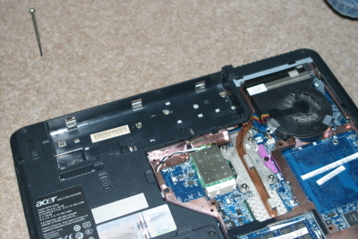
So I set about trying to remove the keyboard without the benefit of a service manual (oh what fun). 🙄 I started by immediately making a big mistake and removing the memory bay/mini pci cover. This is the biggest cover on the base of the laptop and it’s a right shunt to remove. If you ever need to take this one off, remove all the screws you can see in the cover itself and then carefully start levering from the edge nearest the centre of the laptop first. When I say ‘carefully’, I mean eggshells carefully. The plastic is thin and the whole circumference of the cover is fitted with small extrusions which serve as clips. These will bend to an extent as you free them (I had to gingerly run a fine screwdriver around the gap), just hope you don’t break them! You only really need this cover off if you are fitting a Mini PCI or RAM upgrade part.

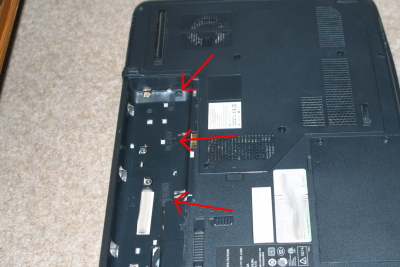
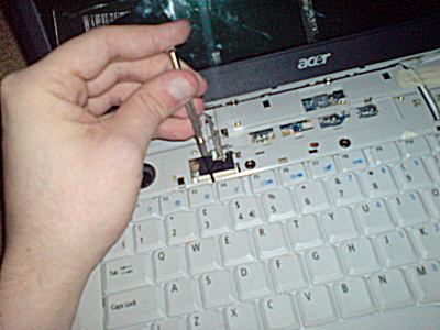
Having discovered there was no access to the keyboard fixings from this cover, I refitted it (also very carefully!) and looked under the battery cover. There I found three black screws which appeared to correspond to the cover above the keyboard on the upper side of the laptop.

Aspire 5315 Keyboard Removal, 3 black screws (arrowed)

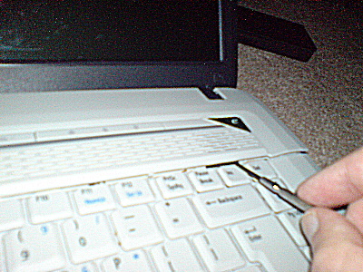
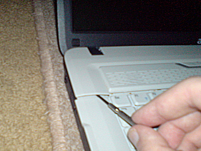
After removing the three black screws, I began levering up the edge of the fascia panel nearest the keyboard. This panel serves to hold the keyboard in place, it also comprises the button cover for the power switchgear and grilles for the speakers. I used a fine jewellers screwdriver to carefully lever the panel up. Again, it’s a series of brittle-looking plastic clips.

Aspire 5315 Keyboard Removal 1

Aspire 5315 Keyboard Removal 2

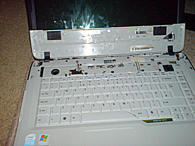
Once the bottom edge of the cover was freed, I lifted it away from the top edge revealing the clips that hold the keyboard in place (set of plastic tabs holding the top edge of the keyboard).

Aspire 5315 Keyboard Top Cover

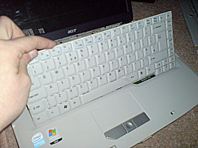
Again, with my trust jeweller’s driver, I levered the top edge of the keyboard from the retaining tabs and not knowing how much ribbon cable existed, gingerly rotated the keyboard up.

Aspire 5315 Keyboard Removal 4

Aspire 5315 Keyboard Removal 5

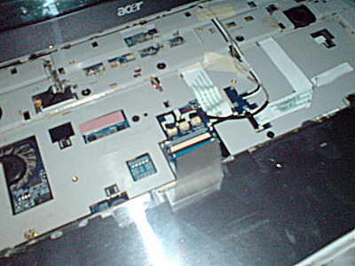
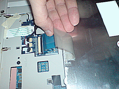
As it turns out, there’s enough ribbon to fold the keyboard all the way over to allow removal of the cable. To release the ribbon cable, you have to carefully lever the dark/black locking collar back along the ribbon until it is out of the socket. After carefully memorising the way the cable fits, withdraw the ribbon.

Aspire 5315 Ribbon Access

Aspire 5315 Keyboard Ribbon Cable Removal Closeup

There’s not much else you can get access to from the keyboard bay, there’s no upgradeable parts here and you can only clean (not remove) the CPU fan from here.

The keyboard is a pretty much sealed unit, I had a little try at soaking it in isopropyl alcohol but to no avail. The sugar in the cola had aparently ‘eaten’ (dissolved) the insulator between the membranes and this was now an ex-keyboard.

Aspire Keyboard Soaking in Isopropyl Alcohol

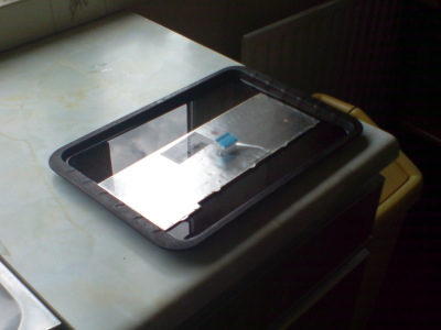
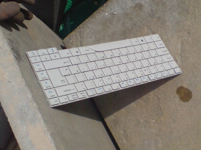
Broken Aspire Keyboard drying in the sun

I managed to find a new keyboard at ‘Acer Spare Parts‘, a company in the UK who had the part shipped in to from Ireland. As my poor luck would have it, the keyboard was damaged in transit possibly because of not-stiff-enough packaging but more likely from ‘courier delivery’ 😉 .

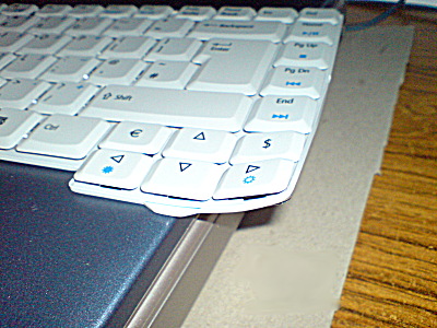
Aspire 5315 new keyboard, bent in transit

I managed to flatten the keyboard out by hand, the metal backplane was quite malleable and there was no physical damage to the keys. Refitting is pretty much the reverse of removal. Make sure you get the ribbon cable the right way round and push the locking collar back up. Then put the keyboard back with the bottom edge in first, press the top edge in (ensure that all the tabs are visible above the rim of the keyboard. The upper cover goes back on top-edge first and then presses down. Finally, three black screws go back into the battery bay and you’re done. (Boot and test the keyboard)

This method may work for other Acer Aspire models. Some of the Apire 5000 such as the 5050, 5520 and 5570 look very much alike and 7000 models certainly look similar but don’t quote me on this.

It’s a relatively simple procedure providing you are fairly dexterous and capable of being very gentle and little bit patient. Still, attempt at your own risk, don’t come crying to me if the whole lot disintegrates in your hands! 😉

[ad name=”articlebox10″]

Gray-Hoverman TV antenna

If you’re a resident of the UK who has adopted (or been forced to adopt) the all-singing, all-dancing and often non-working DVB-T digital television standard, you’ll have probably spent some time cursing your TV aerial or the trees between it and the transmitter. I don’t have any such issues myself, being no great fan of modern television programming but members of my family still insist on vegetating in front of the inane spectacle for hours on end, becoming disconsolate when the ‘entertainment’ carried over the air by UHF radio waves and an MPEG-2 stream is interrupted.

Looking around for an alternative, I saw a revised design of an old antenna design in the web technical digests, namely the Gray-Hoverman antenna. Based on the Hoverman antenna of the 1960s, the now computer modeled design is said to outperform other commercial antennas for limited line of sight applications over long distances.

I’m going to try to evaluate whether the Gray-Hoverman would be useful for UK DVB-T and I’m considering making one myself.

The design is licensed under the GPL v3