Using Linux to Identify Motherboard Model

The most obvious way to identify the make and model of a computer motherboard is to take the cover off the machine and have a look. However, sometimes this isn’t practical or desirable

Ideally, if you’re going to remove a cover from a computer you want to shut it down first. You could do it with the system still running but you’ve only got to drop a case screw into a turning fan to give yourself an expensive day

You may also be unable to directly access the computer which you wish to identify the motherboard within. It could be in another building on a distant site or installed in a server rack which could be time consuming to remove it from.

Linux and dmidecode finds your motherboard info

If your computer is running linux (and in this article we assume that’s exactly what it is running!) you can quickly and easily find the motherboard model using dmidecode.

dmidecode is a tool which interrogates the computer’s System Management BIOS from the command line.

It can read various hardware information with greater or lesser reliability. How solid the information is depends upon how much care and effort the hardware manufacture put into their product.

dmidecode your motherboard from the command line

dmidecode can read various records from SMBIOS but the one in which we are interested in is the motherboard.

To issue the command, you need root (or sudo) privileges either in a terminal on the local machine or via an SSH session remotely.

The required dmidecode command on linux to read motherboard information is:

dmidecode -t 2

If you prefer to be more verbose, the following command will have the same effect:

dmidecode -t baseboard

Where the -t 2 switch instructs dmidecode to read the 2nd table which is “Baseboards” or motherboard as we require.

This should print the motherboard information in a format similar to:

Base Board Information
        Manufacturer: ACME Motherboards
        Product Name: Motherboard 2000
        Version: 2.0
        Serial Number: 12345

dmidecode can also interrogate the SMBIOS tables for a lot of other information about installed hardware.

You can see all of the available tables which dmidecode can read along with the output options by issuing the command:

man dmidecode

Have fun talking to your system and if you use dmidecode for anything particularly clever, or find any unusual output from your system, let us know in the comments below!

Flashing Tasmota on a Sonoff Basic Without Soldering

If you’ve arrived here, the chances are you know what a Sonoff Basic network connected switch is. You may also have an idea what Tasmota firmware is and have an urge to flash your Sonoff Basic.

⚠️Warning: Sonoff network switches are mains-power devices. You mess with them entirely at your own risk! ELECTRICITY CAN KILL!⚠️


The layout of the Sonoff basic switch is super-simple. An ESP32 microcontroller with WiFi controls a relay which can switch the live wire on a 240v 10-amp load. A neutral pass-through is provided but no ground wire.

The Sonoff Basic is designed to be fitted in-line on a power cable to an appliance (a table lamp in my case).

Flashing the Sonoff without any soldering

First of all, if you’re going to flash your Sonoff Basic over serial/GPIO, make absolutely sure the Sonoff is disconnected from mains power (preferrably, completely unwired).

Also bear in mind that my method is a bit Heath-Robinson to avoid soldering so you could break your Sonoff Basic completely or destroy your GPIO flashing device too.

For my flashing method, I used an original model Raspberry Pi Model B as the GPIO host. It just so happened that I had one readily available that I wouldn’t be too upset about if it got fried. I had some 1×40 header pins and DuPont jumper cables from another project.

In order to access the GPIO header, I needed to get the lid off the Sonoff Basic. It’s obviously a push-fit lid but prying it off can be tricky. It’s held by four lugs at the long edges. The best bet seems to be running a finger-nail along the gap to gently force it open.

Sonoff Basic Lid Removed Lugs

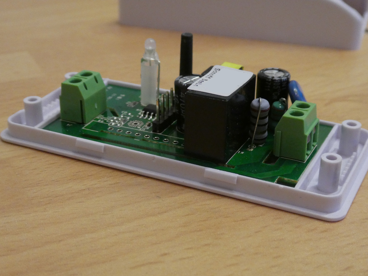
Two of the four lugs that hold the Sonoff Basic’s lid on.

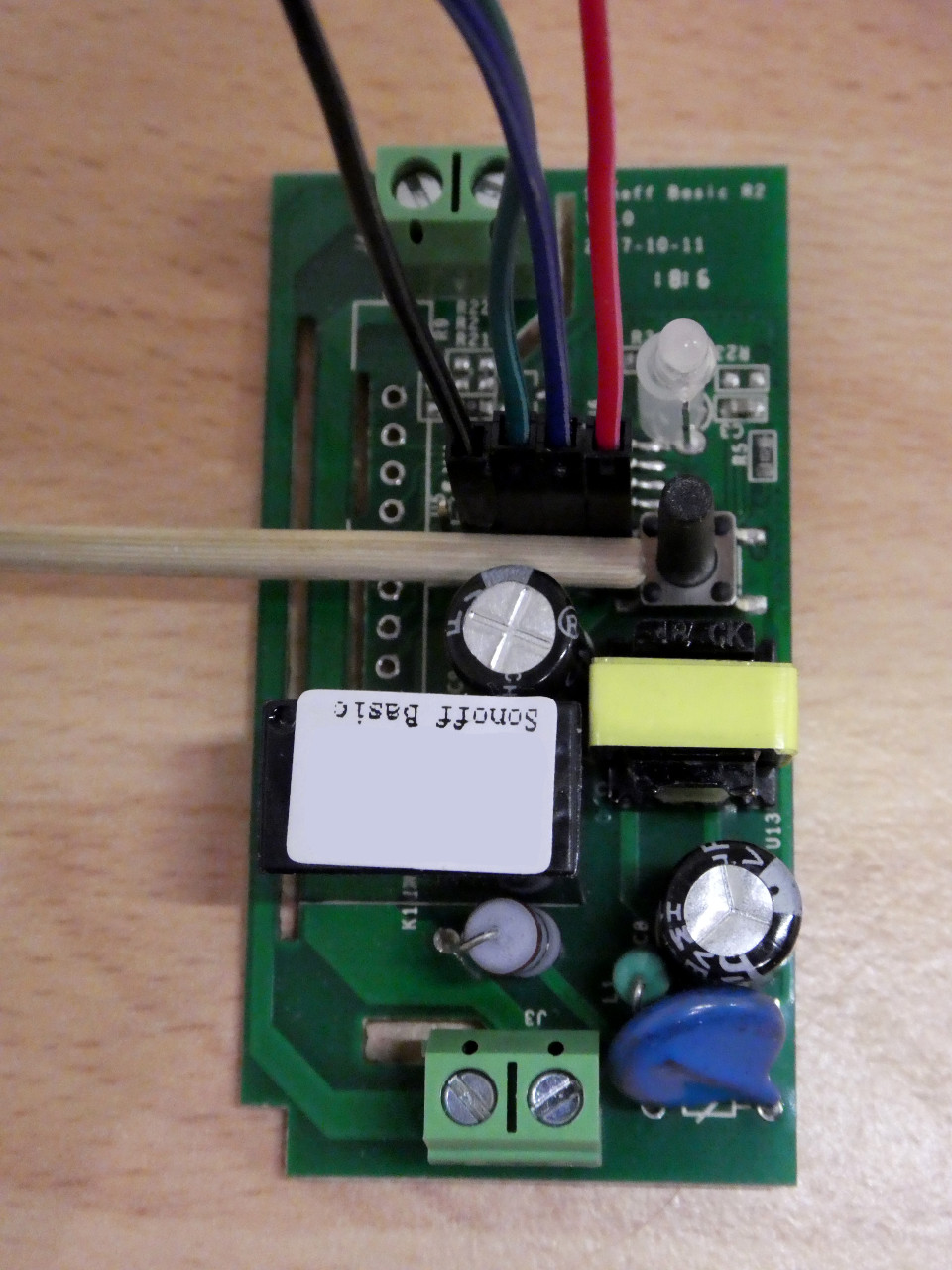
The GPIO connections are in the middle of the PCB next to the microswitch and are unpopulated. Some firmware flashers have soldered directly onto these contacts or soldered header pins in place. I, however, wanted to see if I could get away without any soldering.

Counting away from the microswitch, the GPIO pins are 3.3v, RX, TX and GND. The fifth hole is GPIO 14 and unused.

I broke off a strip of five of my header pins, utilising the fifth hole purely for stability. I pre-connected the four DuPont jumper wires and placed the header pin block into the GPIO holes.

Then, to ensure at least a reasonable contact with the conductors, I used a wood dowel, gently pushed between the plastic DuPont connectors and the capacitor behind them to force the pins tight against the hole edges. (be warned, this is probably quite a good way of damaging your board!)

If you intend to use something other than a wooden dowel, ensure whatever you use in non-conductive!

At the Raspberry Pi Model B side, I connected just the RX and TX and GND cables, leaving the 3.3v off while I installed the required software (esptool etc) as described on the Tasmota wiki.

Getting the right Tasmota firmware

I also needed to download an appropriate Tasmota firmware image. Quite a few people were having trouble with the 6.x versions on the Sonoff Basic so I started out with the 5.14.0 firmware. The file itself being sonoff-classic.bin.

Note: On the Raspberry Pi Model B, I substituted /dev/ttyAMA0 where it stated /dev/ttyS0 in the Tasmota wiki article due to the older naming conventions on that version of the Raspberry Pi.

Getting the Sonoff Basic into flashing mode requires holding down the microswitch while connecting the 3.3v cable to the Raspberry Pi. This can be tricky as the button atop the microswitch is flexible and can un-make the switch without you noticing.

The next step was to erase the flash memory (remove the factory firmware) by having my Raspberry Pi issue:

esptool.py --port /dev/ttyAMA0 erase_flash

This should take just a few seconds and the result (hopefully successful) will be echoed to the console.

I then removed the 3.3v cable to power down the Sonoff.

Then, once again holding down the microswitch, I reconnected the 3.3v cable to power it up.

I had the Raspberry Pi issue:

esptool.py --port /dev/ttyAMA0 write_flash -fm dout 0x0 /path/to/downloaded/sonoff-classic.bin

This takes a little longer as the firmware image is written to the flash memory on the Sonoff.

Once again, I removed the 3.3v power to the GPIO.

Flashing a Sonoff Basic With a Raspberry Pi Model B

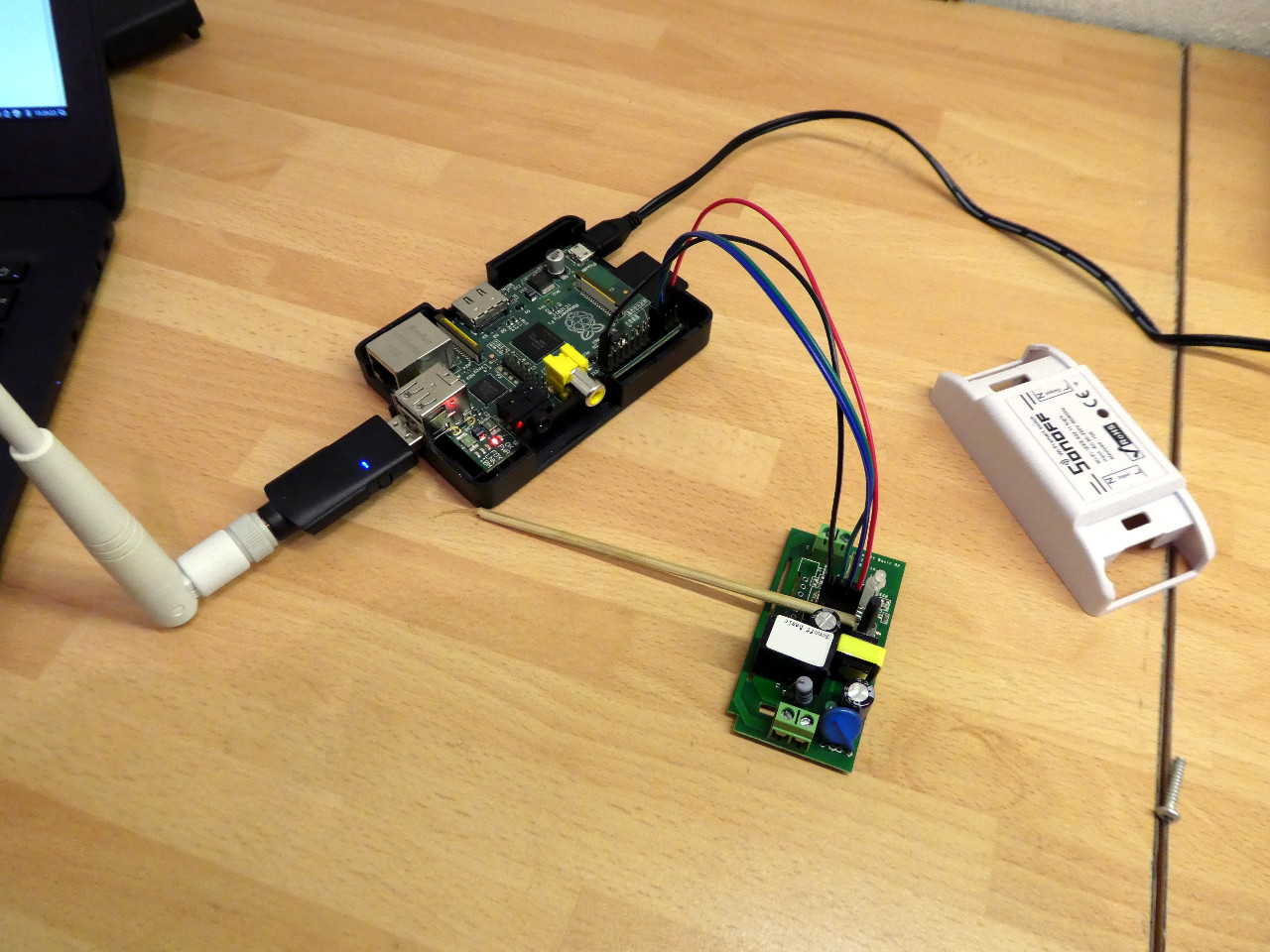
The Sonoff / Raspberry Pi Model B solderless flashing setup

Next, I set up a listening serial terminal on the Raspberry Pi Model B using:

miniterm.py /dev/ttyAMA0 115200 -e

Reconnecting the power to 3.3v pin, this time without pushing the microswitch, causes the Sonoff to boot the Tasmota firmware and echo the output to the Raspberry Pi. Hopefully it all starts well!

Of interesting note, whenever I connected the 3.3v to the Raspberry Pi B, the LEDs on the Pi dimmed for a few moments and the SSH connection to the Pi paused but then recovered. It might be a symptom of my less-than-perfect connection to the Sonoff GPIO pins. Don’t forget, this method is imperfect and could wreck both your Sonoff and your Raspberry Pi!

If you intend to flash many Sonoff Basic units and have access to a 3d printer and some parts, there is a Sonoff Basic programming clip on thingiverse that might help your workflow.

What Next?

To configure my newly installed Tasmota firmware, I used the button-press methods detailed here.

Asus UX305 Screen Brightness Linux Control Fix

If you have an Asus Zenbook UX305 upon which you’ve installed Linux (in this case Linux Mint 18 Sarah) they you may have found that while practically everything works ‘out of the box’, screen brightness control with the Function keys does not.

In fact, on the UX305, I found that while Linux Mint would dim the display after a predetermined period, direct control over screen brightness was not possible using the system-settings panel or the taskbar widget.

After getting sore eyes from what is a very good backlight, I went off in search of a solution. I found a bug report discussing the problem on some newer Asus laptops in Ubuntu over at launchpad.net. The various methods being tried seemed to involve a bit of hit and a lot of miss depending on the hardware platform. However, I found a solution that worked for me with a UX305.

(The following assumes some competence dealing with your system’s internals and don’t forget to back up anything you cant afford to lose!)

To begin with:

Comment #10 on the discussion suggested the following:

In /etc/default/grub add (as root):

acpi_osi=

In the quotes on the line:

GRUB_CMDLINE_LINUX_DEFAULT “”

Not forgetting to then run

update-grub

After rebooting, I tried Function keys F5 and F6 and found they brought up the brightness level overlay and adjusted it but the actual backlight level stayed the same.

Asus UX305 Screen Brightness on Linux

The brightness overlay now working

Next, Comment #69 provided the solution to getting the backlight to actually respond to the backlight control.

First create a file called

20-backlight.conf

in

/usr/share/X11/xorg.conf.d

And add the following lines to the file:

Section “Device”
Identifier “card0”
Driver “intel”
Option “Backlight” “intel_backlight”
BusID “PCI:0:2:0”
EndSection

I then rebooted and found that the Function keys were happily now controlling not just the backlight overlay but the backlight itself.

🙂

It’s not impossible that this fix interferes with some other functionality but I’m yet to encounter any problems.

Bringing Electronics In From The Cold

For those in higher latitudes, it will be becoming colder now as Winter approaches and it’s worth beginning to think about protecting your electronic devices from the cold.

In the Brave New World of the 21st Century, we now have many devices which are easily portable either in your pocket or in your car. Many of these devices, however are not hardened against the cold and the problems it brings.

So, I have a short piece of simple advice for this Winter.

If you have taken a powered-down device out in the cold or left it in a cold place such as your car for a period of time, do not immediately power it on.

It is quite possible as the cool device was moved into a warmer area that moisture could have condensed onto electronic components and provided a potential short circuit waiting to happen.

So, quite simply allow time for the device to warm back up to room-temperature before switching it on. This may take several hours depending on humidity but will allow the condensation to evaporate. It is worth the wait to protect your devices.

Mobile Browsing on the rise

I’ve been noticing in the browsing statistics of various websites with which I am involved that mobile devices (think smartphones) are quite recently becoming very much more noticable.

On one ecommerce site, in a week, I saw nearly ten percent of purchases made using Apple Iphones where last year I would have seen none. The site in question retailed products which were in no way I.T. or telecoms related so this came as quite a surprise. Further, this site was not specifically designed to work with mobile browsers although it did have some design features implemented to make browsing on small-screen devices easier. I’ve also spotted numerous visits from Blackberry and Android OS devices across a broad range of sites.

So, are mobile browsers going to take over the internets?

Probably not but they’re certainly going to be a significant presence. In the West, mobile browsing devices now account for as much as 7% of traffic and the rate is growing quickly. I expect that in the near future there will be a significant push by web developers to provide mobile-native versions of their websites due to this expansion.

Destroying a DVD/CD drive with Gyroscopic Precession

Earlier today, I had one of those classic ‘doh!’ moments.

I had a 5.25in DVD/RW drive externally connected to a virus-infected Windows laptop via USB (running ClamAV if you’re interested).

For some unfathomable reason, I moved the drive with my hand while it was spinning, imparting just a little tilt to it. Even as I did so I knew the result which was about to happen. The CD was already tilting off it’s normal axis of rotation with relation to the drive, trying to maintain it’s original orientation in space due to gyroscopic precession. The inevitable grinding noise indicated that the CD had run out of room to maneuver and collided with the optics / drive internals.

The level of vibration which continued until I yanked out the power was rather impressive; I was glad of the aluminium casing containing the fast moving disc and motor.

I managed to pull the CD tray out and took hold of a CD which was now quite hot around the edges and promptly cut myself on the ground-down and sharpened rim. The drive itself, of course, had ceased to function as a drive of any usable sort.

The moral here is: “Don’t break your own rules”

(Or just don’t be an idiot 😉 )