If you’ve arrived here, the chances are you know what a Sonoff Basic network connected switch is. You may also have an idea what Tasmota firmware is and have an urge to flash your Sonoff Basic.
⚠️Warning: Sonoff network switches are mains-power devices. You mess with them entirely at your own risk! ELECTRICITY CAN KILL!⚠️
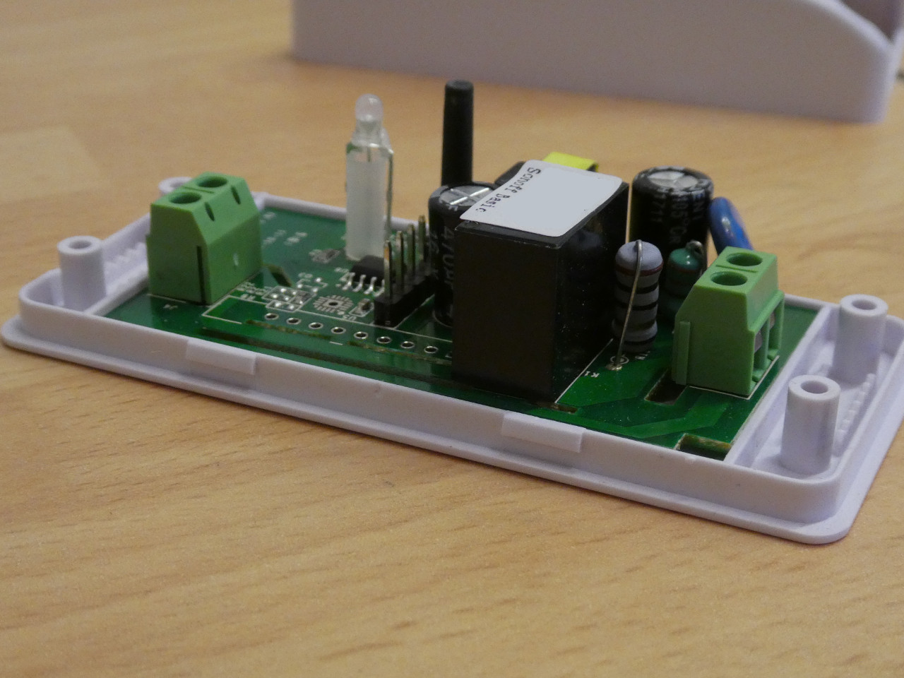
The layout of the Sonoff basic switch is super-simple. An ESP32 microcontroller with WiFi controls a relay which can switch the live wire on a 240v 10-amp load. A neutral pass-through is provided but no ground wire.
The Sonoff Basic is designed to be fitted in-line on a power cable to an appliance (a table lamp in my case).
Flashing the Sonoff without any soldering
First of all, if you’re going to flash your Sonoff Basic over serial/GPIO, make absolutely sure the Sonoff is disconnected from mains power (preferrably, completely unwired).
Also bear in mind that my method is a bit Heath-Robinson to avoid soldering so you could break your Sonoff Basic completely or destroy your GPIO flashing device too.
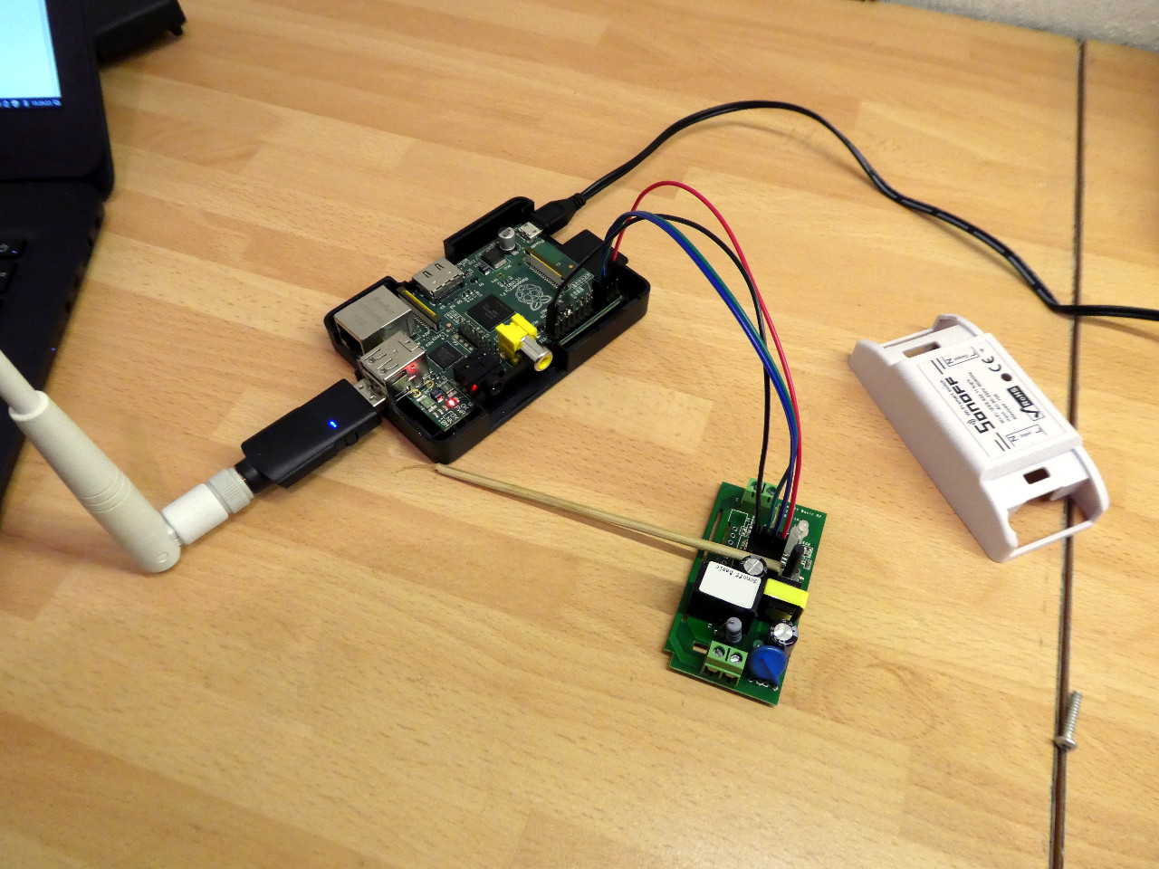
For my flashing method, I used an original model Raspberry Pi Model B as the GPIO host. It just so happened that I had one readily available that I wouldn’t be too upset about if it got fried. I had some 1×40 header pins and DuPont jumper cables from another project.
In order to access the GPIO header, I needed to get the lid off the Sonoff Basic. It’s obviously a push-fit lid but prying it off can be tricky. It’s held by four lugs at the long edges. The best bet seems to be running a finger-nail along the gap to gently force it open.

Two of the four lugs that hold the Sonoff Basic’s lid on.
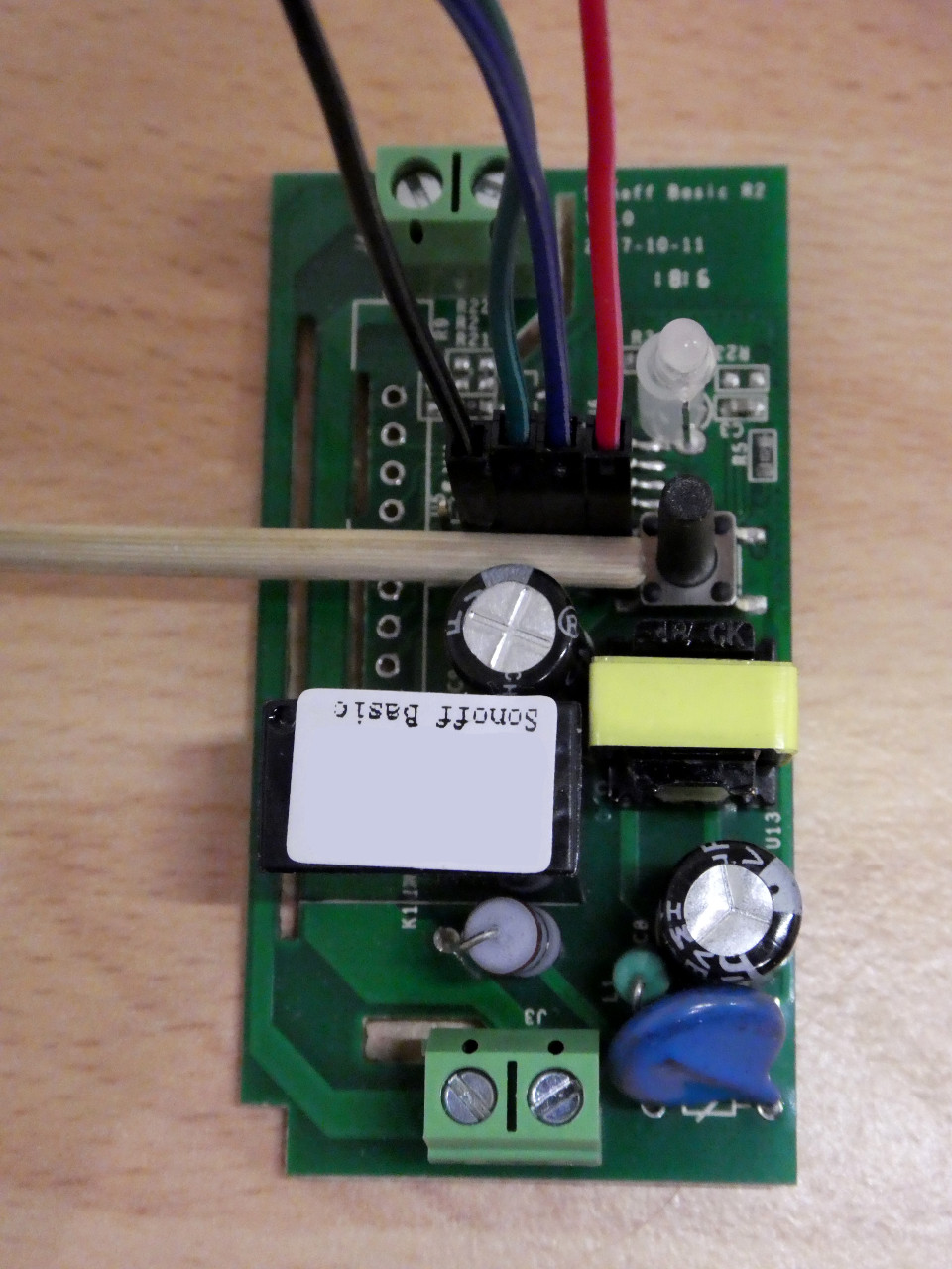
The GPIO connections are in the middle of the PCB next to the microswitch and are unpopulated. Some firmware flashers have soldered directly onto these contacts or soldered header pins in place. I, however, wanted to see if I could get away without any soldering.
Counting away from the microswitch, the GPIO pins are 3.3v, RX, TX and GND. The fifth hole is GPIO 14 and unused.
I broke off a strip of five of my header pins, utilising the fifth hole purely for stability. I pre-connected the four DuPont jumper wires and placed the header pin block into the GPIO holes.
Then, to ensure at least a reasonable contact with the conductors, I used a wood dowel, gently pushed between the plastic DuPont connectors and the capacitor behind them to force the pins tight against the hole edges. (be warned, this is probably quite a good way of damaging your board!)
If you intend to use something other than a wooden dowel, ensure whatever you use in non-conductive!

At the Raspberry Pi Model B side, I connected just the RX and TX and GND cables, leaving the 3.3v off while I installed the required software (esptool etc) as described on the Tasmota wiki.
Getting the right Tasmota firmware
I also needed to download an appropriate Tasmota firmware image. Quite a few people were having trouble with the 6.x versions on the Sonoff Basic so I started out with the 5.14.0 firmware. The file itself being sonoff-classic.bin.
Note: On the Raspberry Pi Model B, I substituted /dev/ttyAMA0 where it stated /dev/ttyS0 in the Tasmota wiki article due to the older naming conventions on that version of the Raspberry Pi.
Getting the Sonoff Basic into flashing mode requires holding down the microswitch while connecting the 3.3v cable to the Raspberry Pi. This can be tricky as the button atop the microswitch is flexible and can un-make the switch without you noticing.
The next step was to erase the flash memory (remove the factory firmware) by having my Raspberry Pi issue:
esptool.py --port /dev/ttyAMA0 erase_flash
This should take just a few seconds and the result (hopefully successful) will be echoed to the console.
I then removed the 3.3v cable to power down the Sonoff.
Then, once again holding down the microswitch, I reconnected the 3.3v cable to power it up.
I had the Raspberry Pi issue:
esptool.py --port /dev/ttyAMA0 write_flash -fm dout 0x0 /path/to/downloaded/sonoff-classic.bin
This takes a little longer as the firmware image is written to the flash memory on the Sonoff.
Once again, I removed the 3.3v power to the GPIO.

The Sonoff / Raspberry Pi Model B solderless flashing setup
Next, I set up a listening serial terminal on the Raspberry Pi Model B using:
miniterm.py /dev/ttyAMA0 115200 -e
Reconnecting the power to 3.3v pin, this time without pushing the microswitch, causes the Sonoff to boot the Tasmota firmware and echo the output to the Raspberry Pi. Hopefully it all starts well!
Of interesting note, whenever I connected the 3.3v to the Raspberry Pi B, the LEDs on the Pi dimmed for a few moments and the SSH connection to the Pi paused but then recovered. It might be a symptom of my less-than-perfect connection to the Sonoff GPIO pins. Don’t forget, this method is imperfect and could wreck both your Sonoff and your Raspberry Pi!
If you intend to flash many Sonoff Basic units and have access to a 3d printer and some parts, there is a Sonoff Basic programming clip on thingiverse that might help your workflow.
What Next?
To configure my newly installed Tasmota firmware, I used the button-press methods detailed here.
